The LC-3

Abstract
- The ISA of LC-3
- Memory Organization
- Registers
- Instruction Set
- Operate
- Data Movement
- Control
- Microarchitecture of LC-3. (Datapath)
Tip
It's worth noting that in the notes I skip many examples on the book. However, if you have not taken the course Assembly Language, or not familiar with programming in assembly language, please read the example on the textbook carefully and practice it sufficiently.
The ISA: Overview
The ISA specifies the memory organization, register set and instruction set, including the opcodes, data types, addressing modes of the instruction in the instruction set.
Memory Organization
- address space: \(2^{16}\) (i.e. 65536) locations.
Not all 65536 addresses are actually used for memory locations. - addressability: 16 bits. We refer to 16 bits as 1 word in the LC-3, so it's also called word-addressable.
Registers
As mentioned before, each register is called a GPR (General Purpose Register). They are referred to as \(R0, R1, \ldots R7\).
Registers store information that can be operated on later, and they are stored register files, where CPU can access them faster than memory.
The Instruction Set
An instruction is made up of its opcode and operands.
The instruction set is defined by its set of opcdeos, data types and addressing modes.
Opcodes
The LC-3 ISA has 15 instructions and the opcode is specified in bit[15:12]. The code 1101 has been left unspecified.
Data Types
Every opcode will interpret the bit patterns of its operands according to the data type it's designed to support.
The same bit pattern can correspound to different number, depending on instructions that interpret it. e.g. ADD R2, R1, #1, LD R2, #1. In ADD, #1 is interpreted as a number for arithmetic, while in LD, #1 is interpreted as an address.
Addressing Modes
An operand can generally be found in one of 3 places: in memory, in a register or as a part of the instruction. If the operand of the instruction, we refer to it as a literal or as an immediate operand.
The LC-3 supports 5 addressing modes: immediate (or literal), register and 3 memory addressing modes: PC-relative, indirect and Base+offset.
The Instruction Set of the LC-3
Operate Instructions
NOT
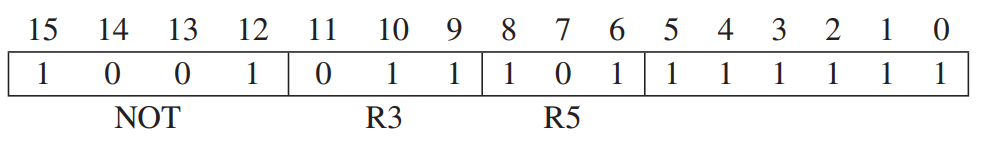
The NOT (opcode=1001) instruction is the only operate instruction that performs a unary operation. bits[11:9] is DR, bits[8:6] is SR, and bits[5:0] are set to 1.
The datapath of NOT is as follows:

For binary operations (like ADD, AND) the datapath is almost the same except the operand B which is also from the register files.
Immdiates In Operate Instructions
The diagram below shows ADD R1, R4, #-2. Note that we the operand B is computed by signed-extending bits[4:0] to 16 bits. And since there is only 5 bits to store immediates, not all 2's complement intergers can be immediate operands. (only \([-16, 15]\))

With the help of NOT and ADD (with immediate), we can implement the substraction. (Recall that in Chapter 2, the negative of an integer represented in 2's complement can be obtained by complementing the number and adding 1)
The LEA Instruction
LEA (opcode=1110) loads the register specified by bits[11:9] of the instruction with the value formed by adding the incremented PC to the sign-extended bits[8:0] of the instruction.
LEA is useful to initiallize a register with an address.
Note that the values to be loaded into the register does not involve any access to memory, and it does not affect CC.

Data Movement Instructions
The process of moving information from memory to a register is caled load, and the process of moving information from a register to a memory is called store.
The LC-3 contains 6 instructions that move formation: LD, LDR, LDI, ST, STR, STI. The format:
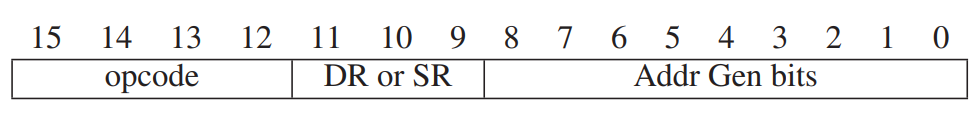
-
PC-Relative Mode: LD and ST
-
Indirect Mode: LDI and STI
-
Base+offset Mode: LDR and STR
Note that laod instructions will influence CC, while store not. The value that is finally read from memory and will be loaded to the register determine CC.
It's also worth noting that if some bits specify DR in load instructions, then it will specify SR in store instructions.
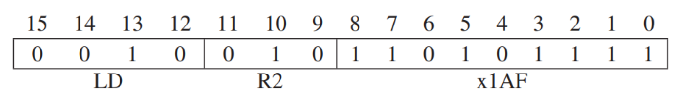
PC-Relative Mode
LD (opcode=0010) and ST (opcode=0011) specify the PC-relative addressing mode.
The memory address is computed by signed-extending bits[8:0] to 16 bits and adding the result to the incremented PC (incremented during FETCH phase).
Note that the address of the memory opearand is limited to a small range. (\([-255,+256]\))

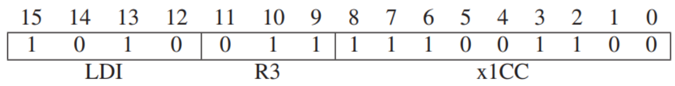
Indirect Mode
LDI (opcode=1010) and STI(opcode=1011) specify the indirect addressing mode.
An address is first formed exactly the same way as with LD, however, the result is the address of the address of the operand. So we need to interrogate memory twice.
Note that the address of the operand can be anywhere.
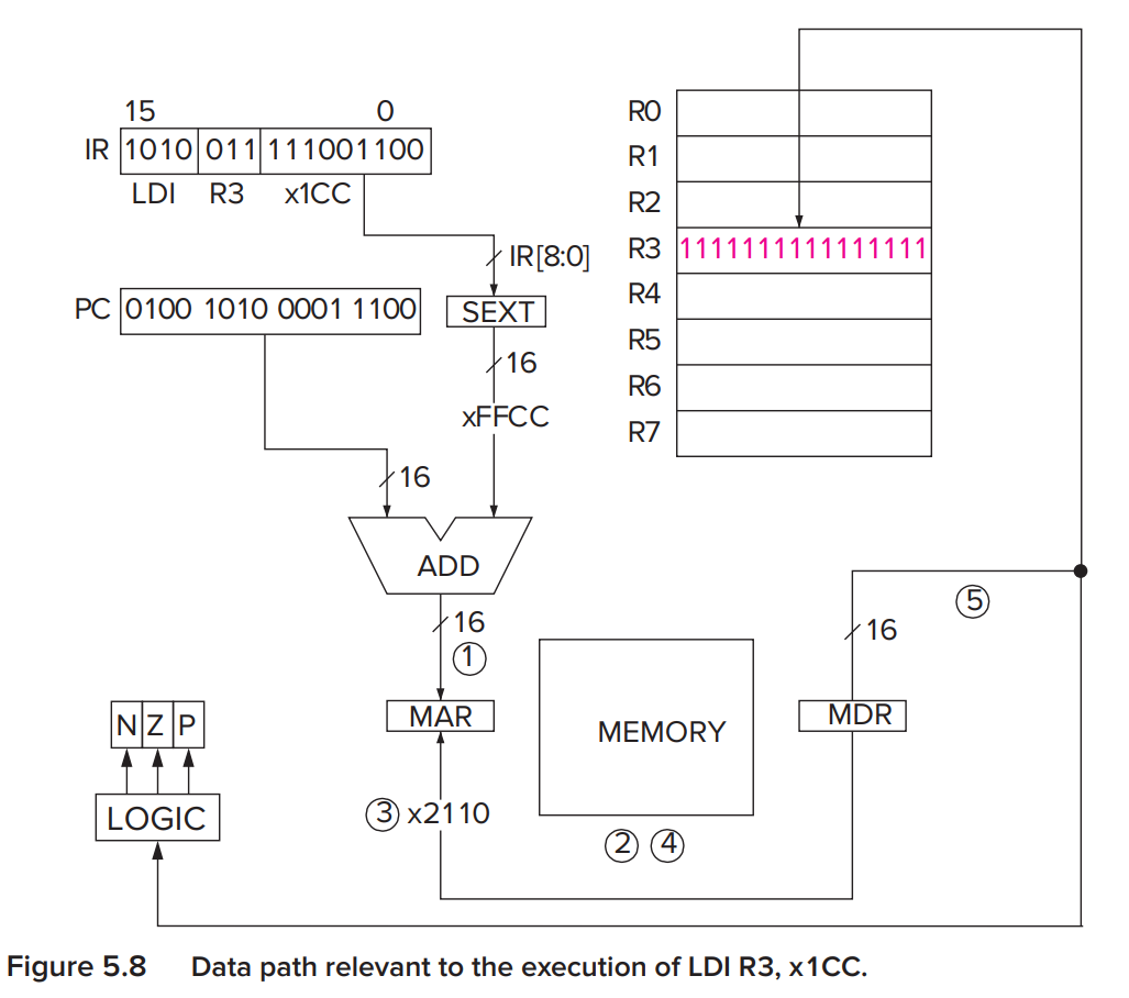
In the example above, the incremented PC is x4A1C and the sign-extended offset is xFFCC. So we first get the address x49E8 and get the data in x49E8, which is x2110. Then we obtain the data in x2110 and load the value into the register R3.
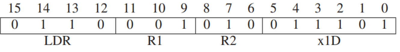
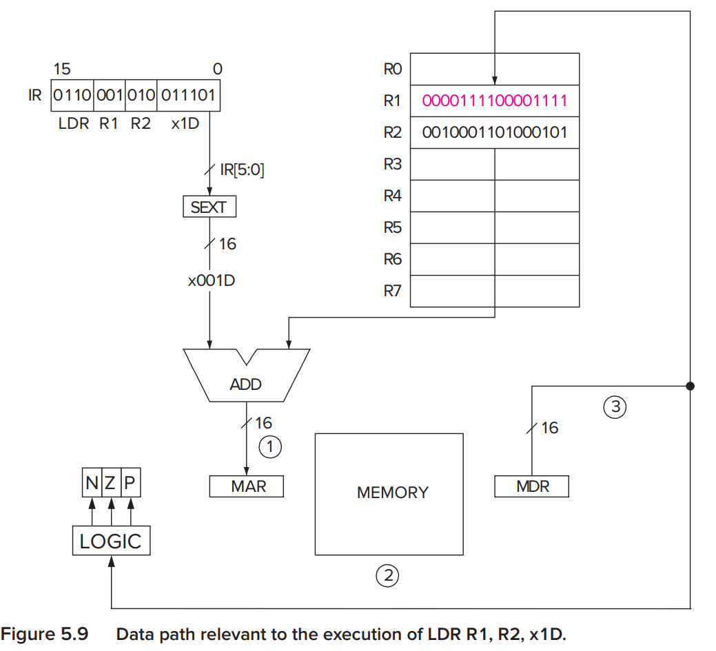
Base+offset Mode
LDR (opcode=0110) and STR (opcode=0111) specify the Base+offset addressing mode.
The address is obtained by adding a signed-extended 6-bit(bits[5:0]) offset to a base register(bits[8:6]).
Note that the address of the operand can also be anywhere.
Control Instructions
The LC-3 has 5 opcodes that enable the sequential execution flow to be broken: conditional branch, unconditional jump, subroutine call( funtion), TRAP (service call) and RTI.
Conditional Branches
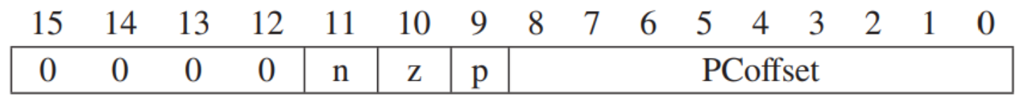
BR (opcode=0000) uses condition codes to determine whether or not to depart from the usual sequential execution. Besides, not all condition codes will be inpected and we can determine which condition codes will be inspected. e.g. In BRz x0D9, bit[11:9]=010 so we only check the condition code Z, which means if the result of the last instruction that can set CC is zero, then we will jump to the target address.
Additionally, if we request to check all condition codes, like BRnzp x0D9, it means an unconditional branch. Since the result of the operation can be positive, negative or zero, so at least one of CC will be set. Meanwhile, if bits[11:9]=000, nothing will happen, just like a nop (an insruction but do nothing and will cause no difference)
In summary, it is only ADD, AND, LD, LDI, LDR, NOT that will change CC after finishing operations.
The JMP Instruction
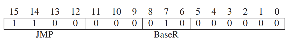
The JMP instruction (opcode=1100) loads the PC with the contents of the register specified by bits[8:6] of the instruction. (its addressing mode is by register)
The TRAP Instruction
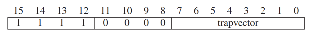
The TRAP instruction (opcode=1111) changes the PC to a memory address that is part of the operating system so that the OS will perform some task on behalf of the program. Once the service call ends, the PC is set to be the address of the instruction following the TRAP instruction.
- Input a character from the keyboard (
trapvector = x23) - Output a character to the monitor (
trapvector = x21) - Halt the program (
trapvector = x25)
Some useful trap service routines are given in the P675 Table A.3. The details of the TRAP instructions will be dicussed in Chapter 9.
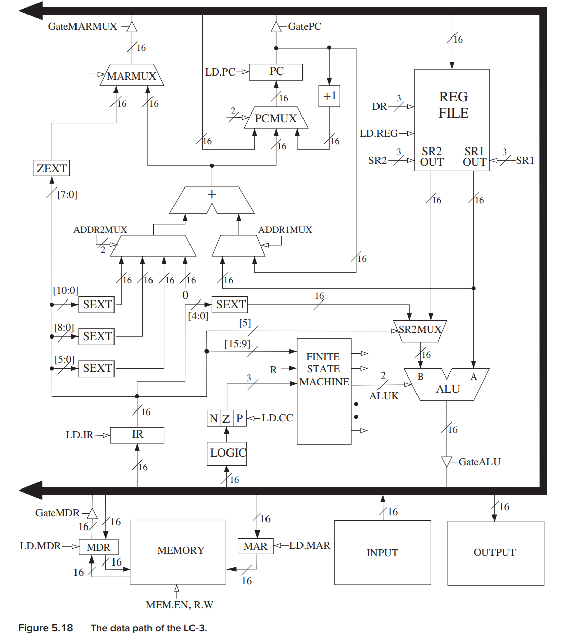
The Datapath
Here is only a figure of LC-3 datapath. Please be clear of the data flow for each instruction and the related control signals. A good way is to draw a datapath on your own hands.
创建日期: 2023年7月5日 20:07:44